Multiple buffer circuit printed circuit board
This was a simple project to design an array of buffer circuits, based on the BUF634P high speed operational amplifier. We made made an easy to manufacture printed circuit board for a more compact and organized circuit.
News
Authors
Description
License
Download
[2013-11-02] First public release!
Original prototype was wired by Joshua Crawford, but the PCB was designed by Andres Cimmarust, which required the scaling up of the circuit. Burkley Patterson and Ana Valdes helped with the initial schematics drawing.
Labs often resort to using devices as DAQ (Data Acquisition) or micro-controller (e.g. Arduino) cards for interfacing equipment with computers. These devices are generally very easy to use but can have an important drawback: limited amount of current output.
In my particular case, I needed to use a National Instruments USB-6009 DAQ device to change the AM voltage of an RF generator driving an AOM. I also recently used an Arduino board for the same purpose. In both these cases, the devices themselves could not actually change the AM voltage of the RF generator. The reason is that the generators I was using in the lab required a minimum current that was above the threshold for my DAQ's.
To get around this recurrent problem in the lab, we simply acquired several BUF634P chips and decided to make an array of buffer circuits with the goal of boosting the current while maintaining the voltage. These BUF634P (manufactured by Texas Instruments) are nothing more than high-speed operational amplifiers engineered specifically to serve as high-speed buffers.
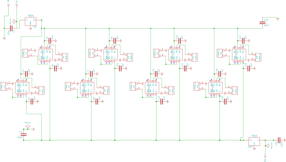
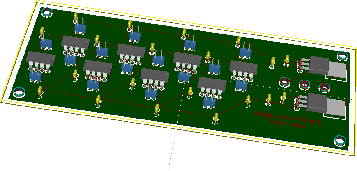
The circuit is straightforward. All we needed to add to the BUF634P were voltage regulators and some capacitors for filtering. Here are a couple of pictures showing the schematics and the PCB. This layout was carried out using the open-source freely available EDA KiCAD.

Fig. 1. Buffer array circuit schematics

Fig. 2. Buffer array circuit populated PCB


