Measuring pulse rise and fall time and signal delay of an AOM
Part II of the UMD Physics Quantum Information Group Rotation course (Spring 2009)
Abstract:
Measurements of pulse rise, fall time and signal delay were carried out on an amplitude modulated Te02 acousto-optic modulator. The laser passed through the AOM and was then focused on a detector. Using a fast oscilloscope, comparison between signals from the detector and the pulse generator allowed the measurement of the desired quantities. The rise and fall times where very close as those reported by the AOM manufacturer. However, the delay was cut in half from the initial measurement by carefully directing the beam as close as possible to the AOM transducer.
Introduction:
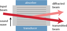
An acousto-optic modulator (AOM) was studied. This device roughly consists of a crystal (in this case TeO2) placed between an absorber and transducer material. The transducer is nothing more than a piezoelectric material which can be controlled to generate a sound wave in the crystal. This wave causes areas of compression and rarefaction in the crystal [1], thus inducing a roughly sinusoidal variation of the index of refraction (see fig. 1). This variation causes incoming light to difract. There are two regimes of operation, one is called the Raman-Nath difraction and the other bragg difraction. Most devices operate in the bragg regime, and this case is no exception.
|
|
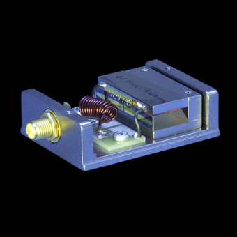
| Fig. 1. Acousto-Optic Modulator diagram [2] | Fig. 2. Acousto-Optic Modulator Example |
The first order difracted beam is not only bent but its frequency changes according to the sound wave frequency. To see this, consider the laser as a stream of photons, and the sound waves in the crystal as phonons, we can apply conservation of momentum and energy to obtain the following expressions for the first order :
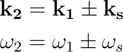
where the +/- sign corresponds to the following geometries:
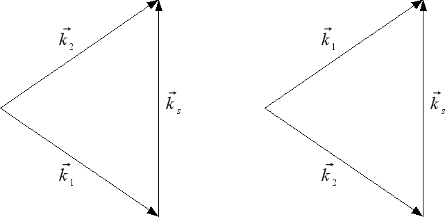
Fig. 3. Addition of wave vectors: frequency up-shift (left) and down-shift (right)
Experiment:
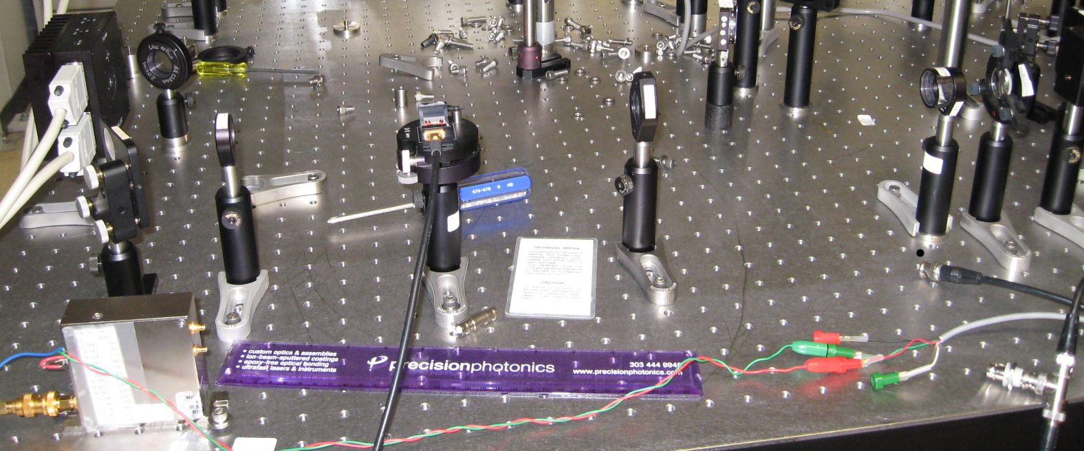
The setup was put in place for the study of the AOM. The same laser was used as well as the steering mirrors. The beam was focused by a lens (f = 15 cm) into the AOM crystal. Then, another lens (f = 17.5 cm) was used to further focus the light to be able to effectively filter the first order diffraction using an iris. Finally, a short-focal-length lens (f = 6.5 cm) was used to converge as much light as possible into the detector (see fig. 4 and/or 5). The output of the detector was connected to Channel 1 of an oscilloscope. The AOM's piezoelectric transducer was controlled by an RF driver that needed a constant 24 V. The driver permitted sound wave frequency modulation via a tunable DC voltage (which we set to 0 V), and amplitude modulation induced with the help of a pulse generator (the duration of the pulse used was roughly 1 µs and an amplitude of 3 V). This junction was connected to channel 4 of the oscilloscope for comparison purposes.
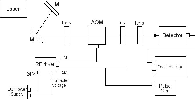
Fig. 4. AOM experiment setup
The following table contains several important specifications about the AOM and its RF driver. These devices were manufactured by Crystal Technology, Inc. AOMO 3080-122 (part #: 97-01280-01) and AODR 1200AF-AEF0-1.0 (part #: 97-02207-17)
| AO medium | TeO2 |
|---|---|
| Acoustic speed | 4.2 mm/µs |
| Frequency Range | 150 - 280 MHz |
| Tunable Voltage | +2 - +15 V |
Table 1. Specifications of the AOM and its RF driver
Results:
With the use of the oscilloscope we were able to trigger on channel 4 (original signal) and thus measure the rise and fall time of the signal from the detector and its delay with respect to the original. Below are the snapshots of the oscilloscope screen:
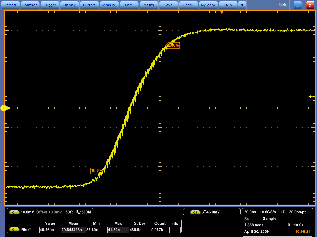
Fig. 6. Rise time (39.85 ns)
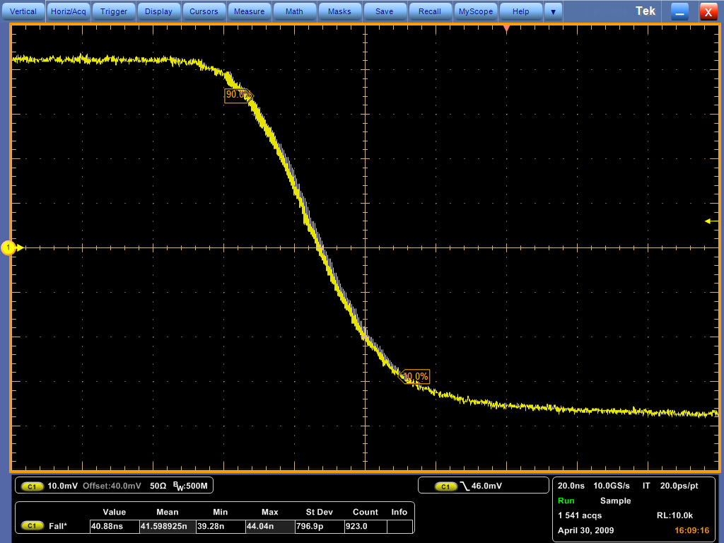
Fig. 7. Fall time (41.60 ns)
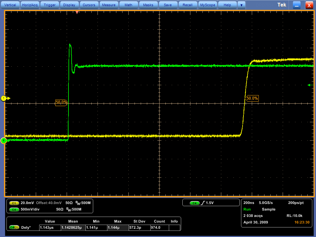
Fig. 8. Rise delay (1.143 µs)
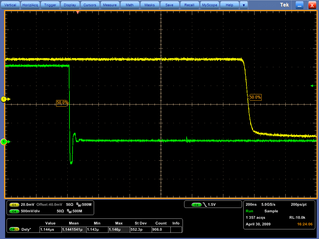
Fig. 9. Fall delay (1.144 µs)
Identifying that the delay is caused by the time it takes for the signal to propagate through the crystal from the transducer to the location of the beam, we were able to cut in half this delay, by directing the beam much closer to the transducer. The snapshots of the oscilloscope can be observed below:
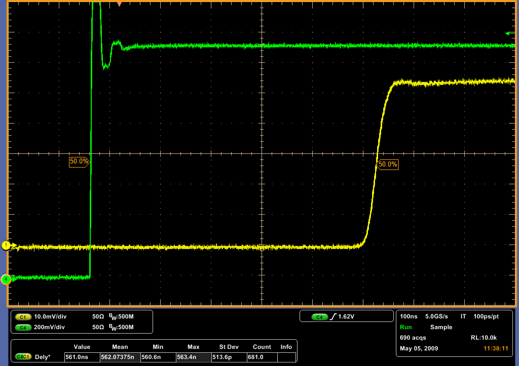
Fig. 10. Improved rise delay (562.1 ns)
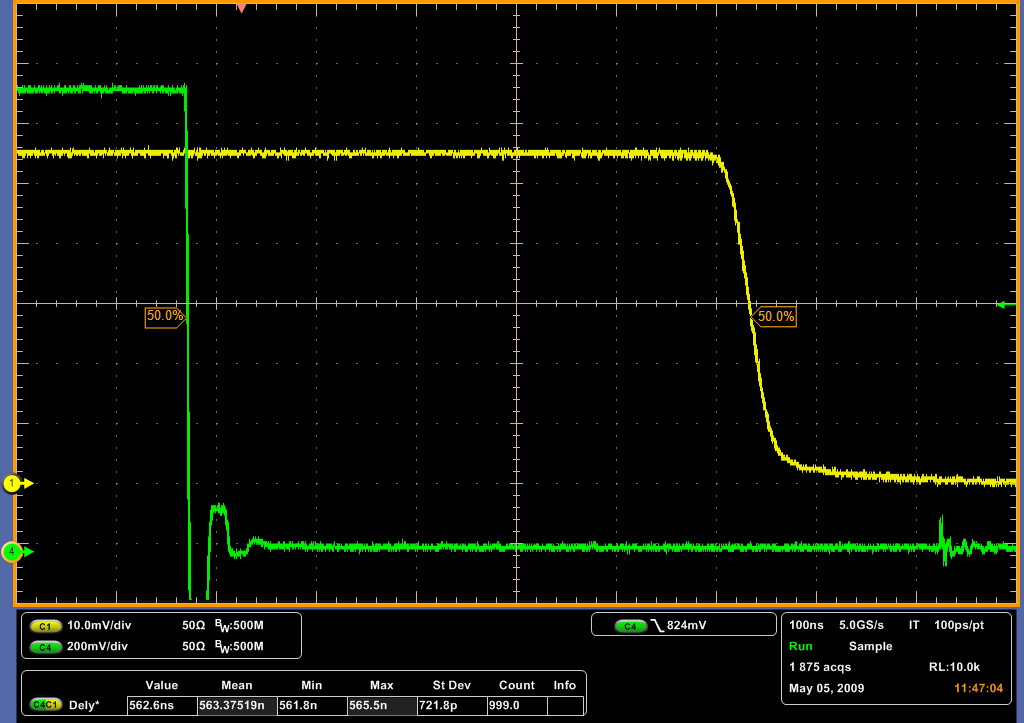
Fig. 11. Improved fall delay (563.4 ns)
Discussion and Conclusions:
The rise and fall time achieved were satisfactory (the goal was to obtain less than 50 ns). This quantity depends on the beam waist, and thus it is difficult to lower it without sacrificing difraction efficiency. The detailed spec sheet for the AOM, states that for a 830 nm laser, and a beam waist of 250 µm, a rise time of 41 ns can be achieved at 80 % efficiency. This closely resembles our results.
The delay was successfully reduced to half its value, by reducing the distance between the transducer and the laser beam. Initially, the beam was at about 5 mm from it. Using the speed of sound in the crystal (see table 2) together with this distance, one can estimate the delay to be of about 1.2 µs, which was our initial delay. Once again, our results coincide with what we expected.
There was a slight discrepancy between rise and fall time. Perhaps this was due to the not completely homogeneous nature of the beam, or to some dust present in the optics. Also, a shorter rise and fall time, might have been achieved by a more collimated and focused beam which could have been obtained by the use of an optical system designed for this purpose.
The notorious transient obtained for the signal coming from the pulse generator (see fig. 14 -17) was, most likely, due to a signal reflection at the junction (see fig. 5). The junction, consisted of a simple T-connector, when it should have also had 50 Ohms resistors on each branch, to equalize the impedance and thus prevent a signal reflection.
Acknowledgements
I would like to thank David Norris for all his help and guidance in the lab, Prof. Luis Orozco for his help, for suggesting the project and for the opportunity to take this course and Elohim Becerra also for his assistance.
References:
- C. C. Davis, Lasers and electro-optics: fundamentals and engineering (Cambridge University Press, 1996).
- R. Paschotta, Acousto-optic Modulators, Encyclopedia of Laser Physics and Technology (2009, March). Retrieved May 10, 2009, from http://www.rp-photonics.com/acousto_optic_modulators.html

