Laser power lock using AOM with Arduino
An acousto-optical modulator (AOM) is a device used to adjust the properties of a beam of light. Incoming light is passed through a crystal that is vibrated with a piezoelectric transducer. The vibrations create localized areas of high and low density that cause the light to diffract like in a grating. By driving the transducer at different frequencies the grating spacing can be adjusted, which shifts the frequency of the diffracted light, and modulating the intensity of the signal adjusts the transmission of the light through the crystal.
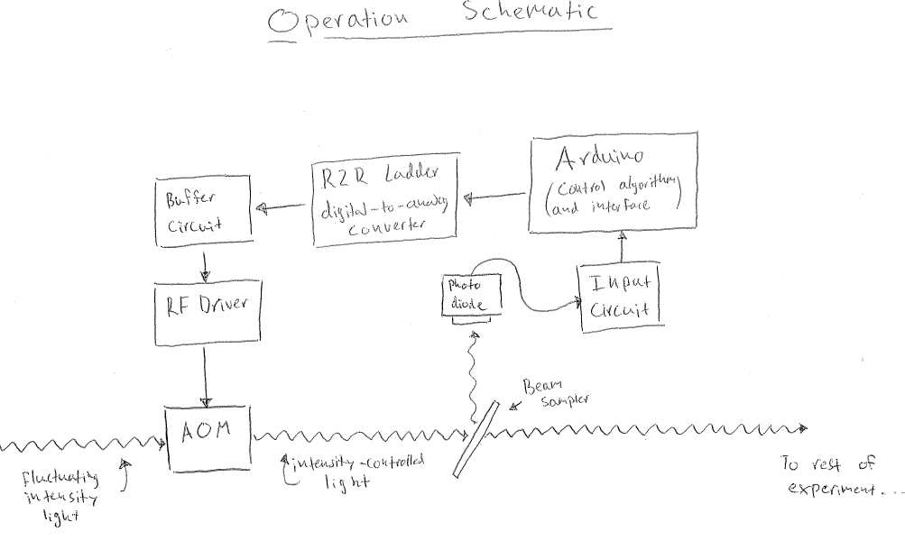
This project takes advantage of the AOM’s ability to adjust its optical transmission in order to stabilize the intensity of a laser beam. We use an AOM, driven by an RF driver. The RF driver accepts two DC voltages as input. One controls the frequency of modulation, and the other controls the intensity. The frequency control is not relevant to this application, but the intensity control input allows us to use the AOM like a variable attenuator. If the light is too bright, we can decrease the transmission, and if it is too dim we can increase the transmission.
We can automate this process by interfacing the system with an Arduino microcontroller. The Arduino constantly monitors the laser intensity by reading the signal produced by a photodiode, and attempts to compensate for any fluctuations by outputting a voltage to the the intensity control input on the RF driver. The voltage output correction is determined by a PID feedback algorithm programmed on the Arduino.
News
Authors
Description
License
Download
How to use
[2013-11-02] First public release!
The code and circuit were put together by Andres Cimmarusti and Burkley Patterson.After the AOM we separate a small sample of the light from the main path with a beam splitter, and monitor its intensity with a photodiode. The beam splitter is a linear optical element, so any percentage fluctuations on the main path are also present on the sample, which means our signal is representative of the light we wish to control.

Fig. 1. Operation schematic for using an Arduino board to control the power of a laser beam.
The photodiode is an unamplified current source, so it is necessary to convert it to a voltage before we are able to read it with the Arduino. For our purposes it is sufficient to pass the current through a resistor to ground, and use the voltage developed across it as our signal. In the input circuit this is done with a trim potentiometer used as variable resistor so we can easily adjust the input sensitivity if necessary. The voltage produced is given by V = I R, and is limited by the maximum voltage of the photodiode. This is particularly advantageous to maximize the sensitivity of the Arduinos readings under the constraints of its limited resolution (10 bits) and maximum input voltage (5v). As an aside, it is good practice to put a ~1k resistor in series with the Arduino input pins to protect it in the event of accidental over-voltage, but it is not necessary.

Fig. 2. Input pseudo-circuit schematic
The Arduino stabilizes the light with a PID algorithm. In this algorithm, the Arduino calculates an error, which is the difference between the current intensity reading (input) and the desired intensity (setpoint). It uses the error to calculate a correction (output), which is given by the sum of the error, integral of the error, and derivative of the error, each weighted by tuning parameters. (Output) = kp*(error) + ki*(time integral of error) + kd*(time derivative of error). In this situation we do not require the derivative correction, so kd is always zero. This algorithm is well known and widely used, and this specific implementation is enabled by an open source PID library.

Fig. 3. Tunings pseudo-circuit schematic
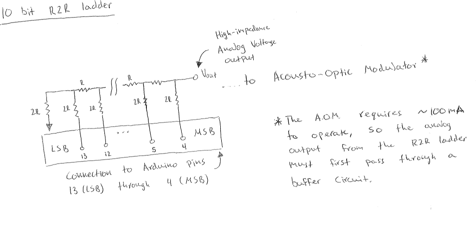
The Arduino only has digital outputs, so it is necessary to devise a scheme of converting a digital output into an analog voltage. Digital-to-analog integrated circuits exist and were available to us, but we decided to use an R2R resistor ladder instead. This is a resistor network with a single output node and as many input nodes as there are bits in the digital signal to be converted. Each node is connected to the network in parallel through a resistor, and each point of connection is connected in series with the output and every other point through a chain of resistors. This configuration weights the input of a node a factor of two lower than the input of the successive node, like bits in a binary number. This creates a one-to-one map between the order of nodes addressed, and the output voltage. With this connected to the Arduino, a byte representing number can be addressed to the digital output pins and converted into an analog voltage.
A technical concern is that this must be done simultaneously, to avoid accidentally outputting incorrect voltages while each pin is changed. The built in digitalwrite() function in the Arduino IDE did not allow for simultaneous or at least rapid switching. Instead it was necessary to use bitwise operations to shift the output byte to map to the Arduino’s port manipulation register. This process is both much faster and simultaneous.

Fig. 4. 10-bit resistor ladder pseudo-circuit showing digital pin connections to an Arduino UNO board.
In the present configuration, the Arduino can produce an analog signal at the rate of tens of kilohertz. It is inconvenient to have the R2R ladder occupy so many pins on the Arduino, and it would be better to connect it through a digital multiplexer instead. This would also avoid the need for port manipulation or messy bitwise math.
On its own the Arduino is not able to source very much current, much less through several kilo-Ohms of resistors in the R2R ladder. The RF driver requires about 100 mA from the input signal, so the current from the Arduino output is boosted through a voltage buffer. This circuit accepts a voltage as input and produces an output with the same voltage but much more available current. The voltage buffer was a separate project and has a write-up of its own.

Fig. 5. Arduino UNO wired to a 10-bit resistor ladder DAC. Also shown are the trim pots that allow tuning of PID loop parameters.
The code is released under the terms of the GNU Public License v3 (GPLv3). For more information please see:
http://www.gnu.org/licenses/gpl-3.0.html
The hardware schematics are released under the terms of the Creative Commons Attribution-ShareAlike 3.0 Unported (CC BY-SA 3.0) license:http://creativecommons.org/licenses/by-sa/3.0/
Source can be obtained from my github here.After assembling the circuit according to the schematics ideas explained in the description and downloading our Arduino source code, it is necessary to install the Arduino IDE software (which is available for Windows, MAC and GNU/Linux).
It is important to download and make the Arduino IDE aware of the PID library. This can be obtained through the Arduino website or github.
Connect the Arduino UNO board via USB cable to your computer and upload the code. This will effectively verify and upload. If there is a problem with the code, the Arduino IDE will throw an error. The power lock should work properly after successfully uploading the code to your arduino board.


